Twelve-pounders are interesting beasties; they are just barely big enough to cram in cheap, common hardware and they are small and light enough to not take much of a weight gain in the way of armor, as most folks are using aluminum or plastic, due to the reduced kinetic load imposed by fairly wimpy weapons. This keeps the price down and the innovation up. I'm currently taking the second Combat Robot construction class offered by the College of San Mateo; it's great fun and amongst other things we're learning how to get the most-est from the least-est. What all our crop of machines have in common is a lowball drive train hacked from cheap battery-operated reversible variable-speed drills that can be had from Harbor Freight for less than $15 a copy. After that the similarities between our bots diverge pretty quickly! We've broken up into teams and the one I'm on this time is called the Six Pack, cuz there's six of us on the team. This will be my second class-built machine and it will be nice to have a team helping out this time around.
I've had my fill of wedge bots. My main objective in building this machine was to see if I could squeeze in some form of pneumatically-activated weapon. All of the bits needed did fit, but I'm afraid the weapon's punch is severely limited by a couple of factors:
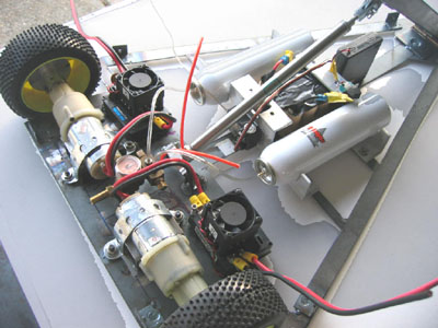
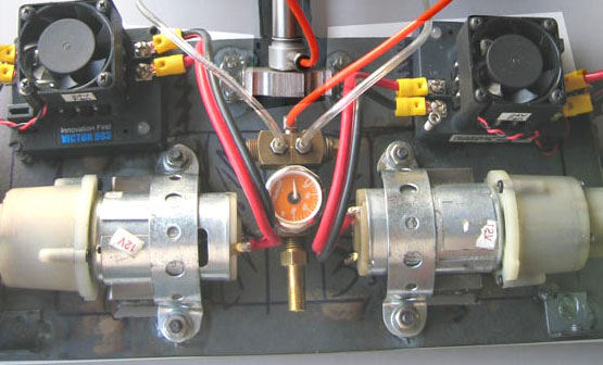
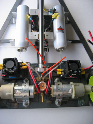
- For starters I couldn't afford the weight of even the lightest CO-2 bottle I could find: a 9 oz bottle weighs a couple of pounds empty. Add to that the weight of a regulator and it's more than half the 12 pound weight limit! The only other tanks I could find weigh virtually nothing, but they can't tolerate CO-2; these are the converted "butane" tanks sold by Robart, which are sufficient to hold air at 150psi, to activate retractable landing gear on model aircraft. Fortunately Robart also offers a complete line of accessories, including a servo-activated valve that is much lighter, cheaper and smaller than anything offered by "industrial" suppliers like Clippard and Bimba, so this option has its merits. The problem is that the tanks, in addition to having a fairly limited 150psi max pressure, have a tiny orifice in the form of a 1/16" i.d. barbed fitting which is small enough that it acts as a flow restrictor. I dodged this problem by hooking four bottles in parallel to a homebrew manifold, but there's another still one more bottleneck!
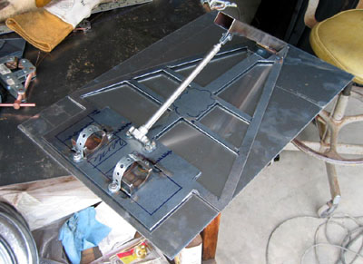
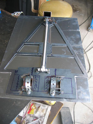
- Air from the manifold has to pass through some sort of control valve on its way to the weapon (a Clippard 0.5-in. bore, 7-in. stroke double-acting pneumatic cylinder). Instead of using the Robart piston valve, which requires a servo to operate it (slowing response time considerably), I opted for a $75.- Pneumatic Activation Switch, aka a solenoid valve that comes wired to connect to the reciever's 3rd channel. This was simple in theory, but again, in practice, it's turned out to be a pig in a poke. The show-stopper: it's threaded 2mm and the hose fittings have i.d.s even smaller than the air tank fittings! On top of that they're metric and don't interface with any of the other fittings. I tried contacting the company directly to see if they could divulge the source of these valves, but my email bounced!! After a chat with the Bimba pneumatics salesman the other day, though, I believe these solenoid valves might be made by Festo Pneumatics, but their website has the Byzantine construction of mature companies that haven't seen the need for a customer oriented website. In the end I talked to the traveling sales rep from Clippard; they sell fittings that are threaded metric, but have SAE hose barbs, so I don't have to stay metric for very long. I'd like to use a Clippard solenoid valve instead, but I don't have a clue how to wire the thing up (neither does Clippard!!), how to power it or where to fit it or how to compensate for the added weight. Hopefully I'll be able to sort these things out before the next round of contests begin...
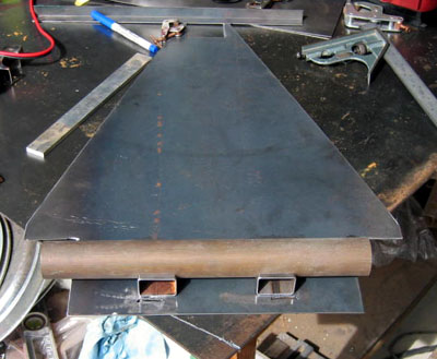
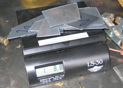
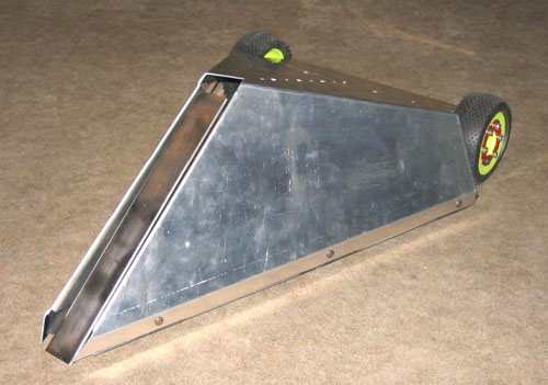
I decided to start with a chassis made from a piece of 1/16" sheet steel, as I'm proficient at welding this material; lots of welding would save on fastener weight, too. First I placed all of the essential components on the workbench and then I measured around their perimeter. I then had a rough idea of the width of the drive train and the length of a flipping arm, so I cut out a triangular piece of steel that would encompass these elements. Next I positioned the components on the steel plate and drew lines around them. I removed the components and began removing unneeded real estate with a plasma torch. By the time I was finished the baseplate had shed a whopping 24 oz. The trimmed base plate is a little floppy, but structural stiffness is restored by attaching the armor via bits of 1/16" angle that have been welded along the edges.
When it comes to the business of driving a bot and of dealing with controlling the motors I am reminded of a stastistic I learned the hard way from Battlebots: 85 % of all system failures were directly attributed to motor controllers failing. My first foray into combat robots was with a 120-lb moddleweight that I built for Battlebots. A teammate who knew about all things electronic suggested that I use a pair of Victor 883s to run my two: 2-hp motors. It turns out they were overtaxed and cooked seconds after my first fight began. I recently found a guy in Silicon Valley who rebuilt them for a little less than half the cost of new ones. With this bit of experience in mind I decided that wimpy motor controllers would not be the weak point on my next machine. I've opted, in this one bit of hardware, to go for massive overkill by using these Victors in my 12-pounder. The pair of them add 8 oz to the vehicle, plus another ounce of wire and another for an on-off switch, but it's worth the weight penalty for the piece of mind it restores.
Were it not for this extremely kewl class at CSM I could not have made special fittings like angle connectors without a huge hassle. It's really great to have access to big lathes, mills, a stomp shear and a wonderful little press brake; the local steel supply house charges $6.- per cut; in one night at class I earned back triple the cost of tuition and I got a lifetime supply of steel strip and angle in dimensions that just aren't available at the store!
I only wish the class was offered closer to my digs. That 80-mile drive each way is a real grinder!
Here's a list of sources I found for various bits:
Following are construction photos of T-34 B